What is Electricity?
#Understanding Electricity with in 5 minutes
What makes the light bulb glow, the fan rotate? What powers our computers, the cell phones and the iPods? The answer is electricity. But what exactly does the term electricity mean? Here’s a video that will help you understand electricity in just 5 minutes.
#Few Basic related to Electricity
Drift Velocity Drift Current and Electron Mobility
Definition of Drift Velocity
The definition of drift velocity can be understood by imagining the random motion of free electrons in a conductor. The free electrons move in a conductor with random velocities and random directions. When we apply an electric field across the conductor, the randomly moving electrons experience an electrical force in the direction of the field. Due to this field, the electrons do not give up their randomness of motion, but they will shift towards higher potential with their random motion. That means the electrons will drift towards higher potential along with their random motions. Thus, every electron will have a net velocity towards the higher potential end of the conductor, and we refer this net velocity as the drift velocity of electrons. Hopping, you understand the definition of drift velocity. The current due to this drift movement of electrons inside an electrically stressed conductor, is known as drift current. It is needless to say that every electric current is "drift current".
Drift Velocity and Mobility
There are always some free electrons inside any metal at room temperature. More scientifically, at any temperature above the absolute zero, there must be at least some free electrons if the substance is conductive such as metal. These free electrons inside the conductor move randomly and frequently collide with heavier atoms and change their direction of motion every time. When a steady electric field is applied to the conductor, the electrons start moving towards the positive terminal of the applied electrical potential difference. But this movement of electrons does not happen in a straight way.
During travelling towards the positive potential, the electrons continuously collide with the atoms and bounced back randomly. During the collision the electrons lose some of their kinetic energy and again due to the presence of electric field, they are re-accelerated towards the positive potential and regain their kinetic energy. Again, during the further collisions, the electrons partly lose their kinetic energy in the same manner. Thus the applied electric field cannot stop the random motion of the electrons inside a conductor. Although in the presence of the applied electric field, the motions of the electrons are still random, there will be a resultant overall movement of electrons towards positive terminals.
In other words, the applied electric field makes the electrons to drift towards positive terminal. That means the electrons get an average drift velocity. If electric field intensity gets increased the electrons are accelerated more rapidly towards positive potential after each collision. Consequently, the electrons gain more average drift velocity towards positive potential, i.e. in the direction opposite to the applied electric field.
If ν is the drift velocity and E is the applied electric field.
 Where, μe is referred as electron mobility.
During travelling towards the positive potential, the electrons continuously collide with the atoms and bounced back randomly. During the collision the electrons lose some of their kinetic energy and again due to the presence of electric field, they are re-accelerated towards the positive potential and regain their kinetic energy. Again, during the further collisions, the electrons partly lose their kinetic energy in the same manner. Thus the applied electric field cannot stop the random motion of the electrons inside a conductor. Although in the presence of the applied electric field, the motions of the electrons are still random, there will be a resultant overall movement of electrons towards positive terminals.
In other words, the applied electric field makes the electrons to drift towards positive terminal. That means the electrons get an average drift velocity. If electric field intensity gets increased the electrons are accelerated more rapidly towards positive potential after each collision. Consequently, the electrons gain more average drift velocity towards positive potential, i.e. in the direction opposite to the applied electric field.
If ν is the drift velocity and E is the applied electric field.
Where, μe is referred as electron mobility.
Where, μe is referred as electron mobility.Animation of Drift Velocity Drift Current and Electron Mobility
 The current caused by the steady flow of electrons due to drift velocity is called drift current
The current caused by the steady flow of electrons due to drift velocity is called drift currentWhat is Electric Current and Theory of Electricity
What is Electric Current?
When there is a potential difference appeared between two points in a conductive medium electric charge starts flowing from higher potential point to lower potential point to balance the charge distribution between the points. The rate of flow of charge in respect of time is known as electric current.
Current Formula
If q Coulomb electric charge gets transferred between these two points in time t sec, then the current can be calculated as
When there is a potential difference appeared between two points in a conductive medium electric charge starts flowing from higher potential point to lower potential point to balance the charge distribution between the points. The rate of flow of charge in respect of time is known as electric current.
Current FormulaIf q Coulomb electric charge gets transferred between these two points in time t sec, then the current can be calculated as
 In differential form, the current can be represented as
Unit of Current
In differential form, the current can be represented as
Unit of Current
As the current is the ratio of transferred charge to the time taken for this charge transferring we can say one unit current is such a rate of charge transferring in which one Coulomb charge is transferred from one point to another in one second. Hence, unit of current is coulomb / second and it is well known as ampere after the great physicist Andrew Marie Ampere. This is SI unit of electric current.
Theory of Electricity
Current in Metallic Conductor
The main cause of current through a metallic substance is the flow of electrons that is the directional drift of free electrons. In metal, even at room temperature, there are plenty of free electrons exist inside the metallic crystal structure. When electric potential between two points in the metal differs the free electrons which were randomly moving at equilibrium potential condition and also the free electrons supplied by the source (if a source is connected between these two points) now get drifted towards higher potential point due to electrostatic attraction. As each of the electrons has a negative charge of - 1.602 × 10 - 19 coulomb, it can be said that the negative charge gets shifted towards higher potential point. The rate of flow of this negative charge in respect of time is the current in the metal.
The main cause of current through a metallic substance is the flow of electrons that is the directional drift of free electrons. In metal, even at room temperature, there are plenty of free electrons exist inside the metallic crystal structure. When electric potential between two points in the metal differs the free electrons which were randomly moving at equilibrium potential condition and also the free electrons supplied by the source (if a source is connected between these two points) now get drifted towards higher potential point due to electrostatic attraction. As each of the electrons has a negative charge of - 1.602 × 10 - 19 coulomb, it can be said that the negative charge gets shifted towards higher potential point. The rate of flow of this negative charge in respect of time is the current in the metal.
Conventional Direction of Current
Although the flow of electrons or negative charge is from lower potential point to higher potential point but the conventional direction of current is considered from higher potential to lower potential. Although current is mainly caused by the flow of electrons that is the flow of negative charge but previously it was thought that the electrical current is due to the flow of positive change. But now it is proved that the current in a metallic conductor is due to flow of electrons or negative charge but the direction of current is still considered as it was accepted previously that is opposite of flow of electrons. The direction of the current which is considered from a higher potential point to a lower potential point is known as the conventional direction of current.

Although the flow of electrons or negative charge is from lower potential point to higher potential point but the conventional direction of current is considered from higher potential to lower potential. Although current is mainly caused by the flow of electrons that is the flow of negative charge but previously it was thought that the electrical current is due to the flow of positive change. But now it is proved that the current in a metallic conductor is due to flow of electrons or negative charge but the direction of current is still considered as it was accepted previously that is opposite of flow of electrons. The direction of the current which is considered from a higher potential point to a lower potential point is known as the conventional direction of current.
Types of Current
Direct Current
When current flows in one direction either in constant or fluctuating manner the current is called direct current.
Alternating Current
When current flows in one direction either in constant or fluctuating manner the current is called direct current.
Alternating Current
When current flows in either direction alternatingly in a frequency is called alternating current. The average value of an alternating current is zero. The alternating current is measured in RMS value. One main parameter of alternating current is frequency.
Magnetic Effect of Current
When current flows through a conductor there will be a magnetic field surrounding the conductor. The direction of the lines of force of the magnetic field can be determined by right-hand grip rule. If we imagine that we have held the current carrying conductor with our right hand with extended thumb along the direction of the current then four fingers of our right hand indicate the direction of lines of force of the magnetic field.
 When we make a coil with a conductor and current flows through the coil then due to magnetic effect of each conductor of the coil there will be an overall magnetic field surrounding the coil. Here we can also determine the direction of the field by right-hand grip rule. If we hold the current carrying coil with our four fingers along the direction of current in the turns of the coil then the extended thumb indicates the direction of the magnetic field.
When current flows through a conductor there will be a magnetic field surrounding the conductor. The direction of the lines of force of the magnetic field can be determined by right-hand grip rule. If we imagine that we have held the current carrying conductor with our right hand with extended thumb along the direction of the current then four fingers of our right hand indicate the direction of lines of force of the magnetic field.
When we make a coil with a conductor and current flows through the coil then due to magnetic effect of each conductor of the coil there will be an overall magnetic field surrounding the coil. Here we can also determine the direction of the field by right-hand grip rule. If we hold the current carrying coil with our four fingers along the direction of current in the turns of the coil then the extended thumb indicates the direction of the magnetic field.
When we make a coil with a conductor and current flows through the coil then due to magnetic effect of each conductor of the coil there will be an overall magnetic field surrounding the coil. Here we can also determine the direction of the field by right-hand grip rule. If we hold the current carrying coil with our four fingers along the direction of current in the turns of the coil then the extended thumb indicates the direction of the magnetic field.Current in Magnetic Field
When we place a current carrying conductor or a current carrying coil in a magnetic field, a mechanical force acts on the current carrying conductor or coil. This mechanical force depends on the current through the conductor or coil.
When we place a current carrying conductor or a current carrying coil in a magnetic field, a mechanical force acts on the current carrying conductor or coil. This mechanical force depends on the current through the conductor or coil.
Measurement of Current
Depending on the principle of interaction between current and magnetic field one can measure the current. One of the basic instruments to measure the current is pmmc instrument or permanent magnet moving coil instrument. The pmmc instrument is only able to measure direct current. The alternating current can be measured by moving iron instrument where magnetic field created by current through the instrument coil causes movement of a soft iron piece either by attraction or repulsion force. This instrument can also measure direct current. Rectifier type instruments are also used to measure alternating current. Here bridge rectifier is used to rectify alternating current then it is measured with pmmc instrument. Wherever may be the types of current measuring instrument in one word all current measuring instruments are called ammeter. An ammeter is always connected in series with the path of which the current to be measured. When very high current is to be measured we use current transformers to step down current for measuring purpose.
Depending on the principle of interaction between current and magnetic field one can measure the current. One of the basic instruments to measure the current is pmmc instrument or permanent magnet moving coil instrument. The pmmc instrument is only able to measure direct current. The alternating current can be measured by moving iron instrument where magnetic field created by current through the instrument coil causes movement of a soft iron piece either by attraction or repulsion force. This instrument can also measure direct current. Rectifier type instruments are also used to measure alternating current. Here bridge rectifier is used to rectify alternating current then it is measured with pmmc instrument. Wherever may be the types of current measuring instrument in one word all current measuring instruments are called ammeter. An ammeter is always connected in series with the path of which the current to be measured. When very high current is to be measured we use current transformers to step down current for measuring purpose.
Heating Effect of Current
When current flows through a conductor there is a heating effect in the conductor. The loss of power in the conductor is i2R watts. The loss of energy is i2Rt joules. This loss of energy is converted to heat. Hence,
 This is known as Joule's Law of Heating.
When current flows through a conductor there is a heating effect in the conductor. The loss of power in the conductor is i2R watts. The loss of energy is i2Rt joules. This loss of energy is converted to heat. Hence,
This is known as Joule's Law of Heating.
This is known as Joule's Law of Heating. Electric Potential
Similarly, the potential difference between two points is defined as the work required to be done for bringing a unit positive charge from one point to other point.
When a body is charged, it can attract an oppositely charged body and can repulse a similar charged body. That means, the charged body has ability of doing work. That ability of doing work of a charged body is defined as electrical potential of that body.
If two electrically charged bodies are connected by a conductor, the electrons starts flowing from lower potential body to higher potential body, that means current starts flowing from higher potential body to lower potential body depending upon the potential difference of the bodies and resistance of the connecting conductor.
 So, electric potential of a body is its charged condition which determines whether it will take from or give up electric charge to other body.
Electric potential is graded as electrical level, and difference of two such levels, causes current to flow between them. This level must be measured from a reference zero level. The earth potential is taken as zero level. Electric potential above the earth potential is taken as positive potential and the electric potential below the earth potential is negative.
So, electric potential of a body is its charged condition which determines whether it will take from or give up electric charge to other body.
Electric potential is graded as electrical level, and difference of two such levels, causes current to flow between them. This level must be measured from a reference zero level. The earth potential is taken as zero level. Electric potential above the earth potential is taken as positive potential and the electric potential below the earth potential is negative.
The unit of electric potential is volt. To bring a unit charge from one point to another, if one joule work is done, then the potential difference between the points is said to be one volt. So, we can say,
 If one point has electric potential 5 volt, then we can say to bring one coulomb charge from infinity to that point, 5 joule work has to be done.
If one point has potential 5 volt and another point has potential 8 volt, then 8 – 5 or 3 joules work to be done to move one coulomb from first point to second.
If one point has electric potential 5 volt, then we can say to bring one coulomb charge from infinity to that point, 5 joule work has to be done.
If one point has potential 5 volt and another point has potential 8 volt, then 8 – 5 or 3 joules work to be done to move one coulomb from first point to second.
Similarly, the potential difference between two points is defined as the work required to be done for bringing a unit positive charge from one point to other point.
When a body is charged, it can attract an oppositely charged body and can repulse a similar charged body. That means, the charged body has ability of doing work. That ability of doing work of a charged body is defined as electrical potential of that body.
When a body is charged, it can attract an oppositely charged body and can repulse a similar charged body. That means, the charged body has ability of doing work. That ability of doing work of a charged body is defined as electrical potential of that body.
If two electrically charged bodies are connected by a conductor, the electrons starts flowing from lower potential body to higher potential body, that means current starts flowing from higher potential body to lower potential body depending upon the potential difference of the bodies and resistance of the connecting conductor.
So, electric potential of a body is its charged condition which determines whether it will take from or give up electric charge to other body.
Electric potential is graded as electrical level, and difference of two such levels, causes current to flow between them. This level must be measured from a reference zero level. The earth potential is taken as zero level. Electric potential above the earth potential is taken as positive potential and the electric potential below the earth potential is negative.
The unit of electric potential is volt. To bring a unit charge from one point to another, if one joule work is done, then the potential difference between the points is said to be one volt. So, we can say,
If one point has electric potential 5 volt, then we can say to bring one coulomb charge from infinity to that point, 5 joule work has to be done.
If one point has potential 5 volt and another point has potential 8 volt, then 8 – 5 or 3 joules work to be done to move one coulomb from first point to second.
If one point has electric potential 5 volt, then we can say to bring one coulomb charge from infinity to that point, 5 joule work has to be done.
If one point has potential 5 volt and another point has potential 8 volt, then 8 – 5 or 3 joules work to be done to move one coulomb from first point to second. Potential at a Point due to Point Charge
Let us take a positive charge + Q in the space. Let us imagine a point at a distance x from the said charge + Q. Now we place a unit positive charge at that point. As per Coulomb’s law, the unit positive charge will experience a force,
 Now, let us move this unit positive charge, by a small distance dx towards charge Q.
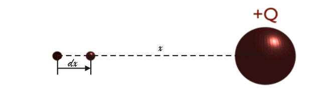 During this movement the work done against the field is,
 So, total work to be done for bringing the positive unit charge from infinity to distance x, is given by,
 As per definition, this is the electric potential of the point due to charge + Q. So, we can write,
 Potential Difference between Two Points
Let us take a positive charge + Q in the space. Let us imagine a point at a distance x from the said charge + Q. Now we place a unit positive charge at that point. As per Coulomb’s law, the unit positive charge will experience a force,
Now, let us move this unit positive charge, by a small distance dx towards charge Q.
During this movement the work done against the field is,
So, total work to be done for bringing the positive unit charge from infinity to distance x, is given by,
As per definition, this is the electric potential of the point due to charge + Q. So, we can write,
Potential Difference between Two Points
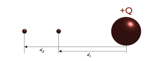 Let us consider two points at distance d1meter and d2 meter from a charge +Q.
We can express the electric potential at the point d1 meter away from +Q, as,
Let us consider two points at distance d1meter and d2 meter from a charge +Q.
We can express the electric potential at the point d1 meter away from +Q, as,
 We can express the electric potential at the point d2 meter away from +Q, as,
 Thus, the potential difference between these two points is
Let us consider two points at distance d1meter and d2 meter from a charge +Q.
We can express the electric potential at the point d1 meter away from +Q, as,
We can express the electric potential at the point d2 meter away from +Q, as,
Thus, the potential difference between these two points is
Voltage or Electric Potential Difference
Before understanding voltage or electric potential difference we should fist investigate how a charged particle moves in uniform static electric field.
Before understanding voltage or electric potential difference we should fist investigate how a charged particle moves in uniform static electric field.
Voltage Theory
Let us consider two parallel plates, that are connected to a battery. The upper plate is connected with positive terminal of a battery. Hence this plate is positively charged, and the lower plate is connected to negative terminal of the battery and hence this lower plate is negatively charged.
These plates produce a static electric field between them which is proportional to surface charge density of both plates, let's the surface charge density of the upper plate is σ. Then the surface charge density of lower plate will be - σ. The electric field produced by the only positive plate is surface charge density divided by twice of permeability of the space between the plates i.e.
 similarly static electric field produced by only negative plate is
 Hence resultant electric field between the plates is
 Let us now assume a positively charged particle enters into that electric field. If the particle has a charge of q Coulomb, then electrostatic force applied on that particle will be
Fe = q.E
Where, E is the electric field vector and it is constant for a uniform electric field.
Now acceleration of the particle,
 Where, m is the mass of the particle.
Hence velocity of the particle at any instant
Where, m is the mass of the particle.
Hence velocity of the particle at any instant t
can be written as,
 Where, vo is the initial velocity of the particle at entrance into uniform electric field.
 So, position of the particle at any instant t can be written as,
 Where, po is the initial position of the particle at entrance into uniform electric field.
 The path is the function of a parabola. Hence it can be predicted from the function that the motion of a charged particle in a uniform electric field is projectile motion in a parabolic path.
These plates produce a static electric field between them which is proportional to surface charge density of both plates, let's the surface charge density of the upper plate is σ. Then the surface charge density of lower plate will be - σ. The electric field produced by the only positive plate is surface charge density divided by twice of permeability of the space between the plates i.e.
similarly static electric field produced by only negative plate is
Hence resultant electric field between the plates is
Let us now assume a positively charged particle enters into that electric field. If the particle has a charge of q Coulomb, then electrostatic force applied on that particle will be
Now acceleration of the particle,
Where, m is the mass of the particle.
Hence velocity of the particle at any instant
Where, vo is the initial velocity of the particle at entrance into uniform electric field.
Where, m is the mass of the particle.
Hence velocity of the particle at any instant tcan be written as,
Where, vo is the initial velocity of the particle at entrance into uniform electric field.
So, position of the particle at any instant t can be written as,
Where, po is the initial position of the particle at entrance into uniform electric field.
Where, po is the initial position of the particle at entrance into uniform electric field.
The path is the function of a parabola. Hence it can be predicted from the function that the motion of a charged particle in a uniform electric field is projectile motion in a parabolic path.
Electrical Potential Difference and Definition of Voltage
We can use electric field vector to characterize static electric field in space. By observing the movement of charged particles inside an electric field, one can predict the exact characteristics of that field. If the field is strong enough, the deflection of a charged particle in a parabolic path will be sharper, and if the field is weak, deflection is less. But it is not the practical way of measuring the intensity of an electric field. Another physical quantity is there which is much easier to measure and also used to characterise an electric field, and this quantity is known as electric potential difference.
 Electrical potential V(t) of a position in the electrical field is such that, electric potential energy is required to place a particle of charge q at that position, would be the product of charge of the particle q and the potential of that position V(t). That is potential energy U(t) = q.V(t).
The SI unit of electrical potential is Volt after name of Italian physicist Alessandro Volta (1745 - 1827).
Voltmeter is used to measure the potential difference between two points.
There is a misconception about potential and voltage. Many of us think that both are the same. But voltage is not exactly potential; it is the measure of electric potential difference of two points.
Electrical potential V(t) of a position in the electrical field is such that, electric potential energy is required to place a particle of charge q at that position, would be the product of charge of the particle q and the potential of that position V(t). That is potential energy U(t) = q.V(t).
The SI unit of electrical potential is Volt after name of Italian physicist Alessandro Volta (1745 - 1827).
Voltmeter is used to measure the potential difference between two points.
There is a misconception about potential and voltage. Many of us think that both are the same. But voltage is not exactly potential; it is the measure of electric potential difference of two points.Electrical Potential and Electrical Field Vector
Electrical potential and electrical field vector, both characterize the same thing that is space of electrical field. Since both electric potential and electrical field vector describe an electric field, they are related.
dV = - E.ds where dV is the potential difference between two points separated by a distance ds and electrical field vector is E.
Definition of Potential Difference or Voltage
After going through the above portion of voltage theory we can now establish a definition of potential difference, definition of voltage in few words. Which says Voltage is the difference in electric potential energy per unit charge between two points. Voltage is the work to be done, upon an unit charge to move between two points, against a static electric field. A voltage which is a measure of electric potential difference, is the cause of electrical current to flow in a closed circuit.
Voltage is the difference in electric potential energy per unit charge between two points. Voltage is the work to be done, upon an unit charge to move between two points, against a static electric field. A voltage which is a measure of electric potential difference, is the cause of electrical current to flow in a closed circuit.
What is Electrical Energy Definition Formula Unit of Electrical Energy
What is Electrical Energy?
Before explaining what electrical energy is, let us try to review the potential difference between two points in an electric field.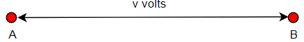 Suppose potential difference between point A and point B in an electric is v volts.
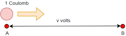 As per the definition of potential difference we can say, if one positive unit electrical charge that is a body containing one-coulomb positive charge travels from point A to point B, it will do v joules work.
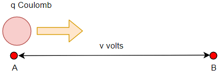 Now instead of one-coulomb charge if q coulomb charge moves from point A to B, it will do vq joules work.
If the time taken by the q coulomb charge to travel from point A to B is t second, then we can write the rate of work done as
 Again, we define the work done per second as power. In that case, the term
would be electrical power. In differential form, we can write, electric power
Again, we define the work done per second as power. In that case, the term
would be electrical power. In differential form, we can write, electric power
Again, we define the work done per second as power. In that case, the term
would be electrical power. In differential form, we can write, electric power
Now, if we place a conductor in between A and B, and through which the quantity of electric charge q coulomb is passing. The charge passing through a cross-section of the conductor per unit time (second) is
 It is nothing but the electric current i, through the conductor.
Now, we can write,
It is nothing but the electric current i, through the conductor.
Now, we can write,
 If this current flows through the conductor for a time t, we can say the total work done by the charge is
 We define this as electrical energy. So, we can say,
It is nothing but the electric current i, through the conductor.
Now, we can write,
If this current flows through the conductor for a time t, we can say the total work done by the charge is
We define this as electrical energy. So, we can say,Electrical Energy Definition
Electrical energy is the work done by electric charge. If current i ampere flows through a conductor or through any other conductive element of potential difference v volts across it, for time t second, the electric energy is,Electrical Energy Formula
The expression of electric power is
The electrical energy is
Unit of Electrical Energy
Basically, we find the unit of electrical energy is joule. This equals to one watt X one second. Commercially, we also use other units of electrical energy, such as watt-hours, kilo watt hours, megawatt hours etc.Watt Hours
If one watt power is being consumed for 1 hour time, the energy consumed is one watt-hour.BOT Unit or Board of Trade Unit or Kwh
The practical, as well as a commercial unit of electrical energy, is kilowatt hour. The fundamental commercial unit is watt-hour and one kilowatt hour implies 1000 watt hours. The electrical supply companies take electric energy charges from their consumer per kilowatt hour unit basis. This kilowatt hour is board of trade unit that is BOT unit.Electric Power
Voltage and current are two basic parameters of an electric circuit. But, only voltage and current are not sufficient to express the behaviour an electric circuit element. We essentially need to know, how much electric power, a circuit element can handle. All of us have seen that a 60 watts electric lamp gives less light than a 100 watts electric lamp. When we pay electric bill for electricity consumption, we are actually paying the cahrges for electric power for a specified period of time. Thus electric power calculation is quite essential for analyzing an electric circuit or network.
Suppose, an element supplies or consumes an energy of dw joules for a time of dt second, then power of the element can be represented as,
 This equation can also be rewritten as,
 Hence, from the as the expression of voltage and current in the equation are instantaneous, the power is also instantaneous. The expressed power is time-varying.
 So, the power of a circuit element is the product of voltage across the element and current through it.
This equation can also be rewritten as,
Hence, from the as the expression of voltage and current in the equation are instantaneous, the power is also instantaneous. The expressed power is time-varying.
So, the power of a circuit element is the product of voltage across the element and current through it.
As we have already told that a circuit element can either absorb or deliver power. We represent the absorption of power by putting a positive sign (+) in the expression of power. Likewise, we put a negative sign (-) when we represent the power delivered by the circuit element.
Passive Sign Convention
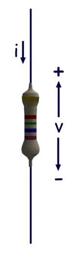
There is a simple relationship between the direction of current, polarity of voltage and sign of the power of a circuit element. We call this simple relationship as passive sign convention. When a current enters in an element through its terminal of positive voltage polarity, we put a positive sign (+) before the product of the voltage and current. This implies that the element absorbs or consumes power from the electric circuit. On the other hand, when the current through the element leaves its terminal of positive voltage polarity, we put a negative sign (-) before the product of the voltage and current. This implies that the element delivers or supplies power to the electric circuit.
Let us take a resistor connected across two circuit terminals. Although, the rest of the circuit is not shown here in the figure. The polarity of the voltage drop across the resistor and the direction of current through the resistor are shown in the figure below. The resistor is consuming a power of vi watts as current i ampere enters in the resistor though its positive side of the dropped voltage v volt, as shown.
 Let us take a battery connected across two circuit terminals. Although, the rest of the circuit is not shown here in the figure. The polarity of the voltage drop across the battery and the direction of current through the battery are shown in the figure below. The battery is delivering a power of vi watts as current i ampere enters in the battery of v volt through its positive polarity terminal as shown.

Let us take a battery connected across two circuit terminals. Although, the rest of the circuit is not shown here in the figure. The polarity of the voltage drop across the battery and the direction of current through the battery are shown in the figure below. The battery is delivering a power of vi watts as current i ampere enters in the battery of v volt through its positive polarity terminal as shown.
Electric Charge
Every matter in this universe is made of atoms. The atoms are electrically neutral. This is because, each atom has equal number of protons and electrons. Protons have positive charge. In an atom, protons sit in the central nucleus along with electrically neutral neutrons. The protons are strongly bounded in the nucleus. So, protons cannot be detached from the nucleus by any normal process. Each electron revolves round the nucleus in definite orbit in the atom. Electrons have negative charge. The quantity of electric charge of an electron is exactly equal to that of a proton but in opposite in nature. The electrons are negative and protons are positive. So, a piece of matter normally electrically neutral, since it is made of electrically neutral atoms.
The electrons are also bounded in the atoms but not all. Few of the electrons which are farthest from the nucleus may be detached by any means. If some of these detachable electrons of neutral atoms of a body, are removed, there will be a deficit of electrons in the body. After, removal of some of the detachable electrons from the neutral body, the total number of protons in the body becomes more than total number of electrons in the body. As a result the body will become positively charged.Not only a body can give away electrons, it may also absorb some extra electrons, supplied from outside. In that case, the body becomes negatively charged.
So, deficit or excess of electrons in a body of matter is called electric charge.
Charge of an electron is very small and it is equal to  . So, total
  number of electrons have electric charge of 1 Coulomb. So, if a body deficits
  number of excess electrons, the body will be of 1 coulomb negative electric charge. number of electrons, the body will be of 1 coulomb positive electric charge. On the other hand, if a body has number of excess electrons, the body will be of 1 coulomb negative electric charge.
. So, total number of electrons have electric charge of 1 Coulomb. So, if a body deficits number of excess electrons, the body will be of 1 coulomb negative electric charge. number of electrons, the body will be of 1 coulomb positive electric charge. On the other hand, if a body has number of excess electrons, the body will be of 1 coulomb negative electric charge.
Charged body is an example of static electricity. This is because, the electric charge is confined in the body itself. Here, the charge is not in motion.
But when the electric charge is in motion, it causes electric current. Electric charge has the potential of doing work. That means it has potential to either attract opposite nature of charge or repulse same nature of charge. A charge is the result of separating electrons and protons.
Electron volt or eV
The concept of electron volt is very simple. Let us start from very basic. We know the unit of power is watt.W = VI, where V is the voltage and I is the current.
Now as I is current, it is nothing but rate of charge transfer. Therefore, instantaneous impression of power would be
 Where, q(t) is the amount of charge transferred in time t.
Where, q(t) is the amount of charge transferred in time t.
Now energy is expressed as
 Where, q is the charge in Coulomb crosses a voltage V volts.
Where, q is the charge in Coulomb crosses a voltage V volts.
From the expression of energy we can write the energy required or work to be done for crossing an electric field of total voltage V by a charge Q coulomb is QV coulomb - volt or joules. Now we know the charge of an electron is - 1.6 × 10⁻¹⁹ coulomb and consider it has crossed an electric field of total voltage 1 V. Then the total work to be done is charge of electron × 1 V.
 This amount of energy is considered as a micro unit of energy called electron-volt.
This amount of energy is considered as a micro unit of energy called electron-volt.Definition of Electron - volt
One electron - volt is the unit of energy in joules which equals to the amount of work to be done for bringing one electron against an electric field of potential difference 1 volt. This is very tiny or micro unit of energy mainly used for different calculation in atomic and electronic levels. The concept of energy levels in the materials is dealt with this micro unit of energy that is electron volt. Not only the energy of electrons, this unit is also used for all types of energy like thermal, light etc.Video Presentation on Electron volt or eV
https://www.youtube.com/watch?v=G-hzdfpIEOI
Sinusoidal Wave Signal
To understand what is Sine wave or Sinusoidal Wave Signal, first let us try to understand what a Signal is.
What is a Signal?
There are different measurable quantities in the world surrounding us. Some quantities are constant like acceleration due to gravity, speed of light, velocity of sound in air. Some are time-varying like AC voltage, Pressure, Temperature. It means they change their value as time passes on. Signal simply means the value of any quantity taken over a period of time. Signals are usually time varying in nature. Generally a graph is plotted between values at different time instants. This is called graphical representation of signal.What is Sine Wave or Sinusoidal Wave Signal?
 Sine Wave or Sinusoidal Wave Signal is a special type of signal. It is given by the function

When Sine wave starts from zero and covers positive values, reaches zero; and again covers negative values, reaches zero, it is said to have completed one cycle or single cycle.
The upper part of sine wave is called positive cycle and the lower part is called negative cycle in a single cycle.
For different values of time, the Signal gives the values of quantity at that time. Therefore Signal is a function of time. It is therefore written asf (t). The Maximum value of the Sinusoidal Signal is also called its amplitude (A). Here ω is called Angular Frequency of Signal and f is the Frequency of Signal. ∅ Is called Phase difference.
Frequency is measured in Hertz (Hz). It shows number of cycles of signal that took place in a second. Large ω or large f value indicates that the signal completes more oscillations (i.e., going from positive values to negative values) in less amount of time. Hence the Signal is more Oscillatory in nature.
Sinusoidal signal need not start at zero. It may start after certain duration of time. This is time after which Sinusoidal Signal starts is indicated with the help of phase difference (∅). It is measured in Radians.
Periodic signals are those which repeat their pattern after certain amount of time. This time after which pattern is repeated is called time period (T) of Periodic Signal. It is inverse of frequency of Signal.
 Sinusoidal signal is a periodic signal, because the pattern keeps on repeating after one Wavelength as shown in the Figure above.
All the power signals in our home, office and industries are AC sinusoidal signals. The frequency (f) in India and British countries is 50 Hz and in American countries it is 60 Hz.
Sinusoidal signal is a periodic signal, because the pattern keeps on repeating after one Wavelength as shown in the Figure above.
All the power signals in our home, office and industries are AC sinusoidal signals. The frequency (f) in India and British countries is 50 Hz and in American countries it is 60 Hz.Why is Sinusoidal Wave Signal so Important?
Sinusoidal signals are important in both electrical and electronic engineering domains. According to Fourier Series Theory, any signal (Periodic Signal) can be written in terms of only sine and cosine Signals of different frequencies. Therefore a complex signal can be broken-down into simple sine and cosine signals and mathematical analysis becomes easy. Hence it is widely used in electrical and electronic analysis. Also, in transformers the output voltage is time derivative of magnetic flux. Magnetic flux is itself time derivative of input voltage. But we want same voltage signal both at input and output. The only functions that satisfy this condition are sine and cosine functions. As sine signal starts from zero value, it is preferred. Therefore majority of power systems in the world today are using sinusoidal AC voltage. All the household equipment also work on Sinusoidal AC voltage.RMS or Root Mean Square Value of AC Signal
Why rms values are used in AC system?
What does an average and rms value mean?
Why all the ratings of AC systems are in rms not in average value?
What is the difference between rms and average value?
These are the questions which come in our minds every time when we are dealing with AC circuits.
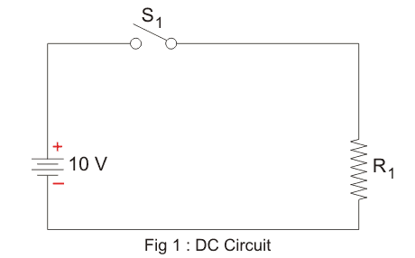
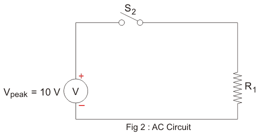
Suppose, we have a simple DC circuit (figure - 1) and we want to replicate it in an AC circuit. We got every thing same, except supply voltage which is now to be an AC supply voltage. Now, the question is what should be the value of AC supply voltage so that our circuit works exactly same as that of DC.
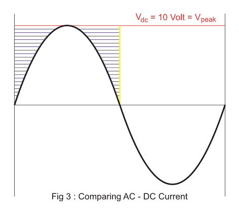
Let us put same value of AC supply voltage (AC Vpeak = 10 volt) which is in our DC circuit. By doing that we can see (figure 3) for a half cycle how the AC voltage signal is not covering up the whole area (blue area) of constant DC voltage, which means our AC signal can not supply the same amount of power as our DC supply
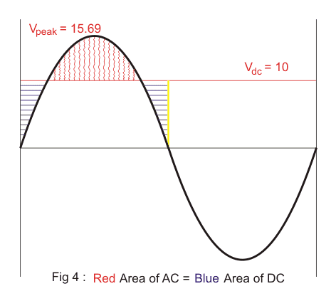
We found that (figure 4) by increasing the peak voltage Vpeak up to (π/2) times of DC supply voltage we can actually cover the whole area of DC in AC. When the AC voltage signal completely represents the DC voltage signal then that value of DC signal is called the average value of AC signal.
 Now our AC voltage should supply the same amount of power. But when we switched-on the supply surprisingly, we found that AC voltage is supplying more power than the DC. Because an average value of AC supplies same amount of charges but not the same amount of power. So, to get same amount of power from our AC supply we must decrease our AC supply voltage.
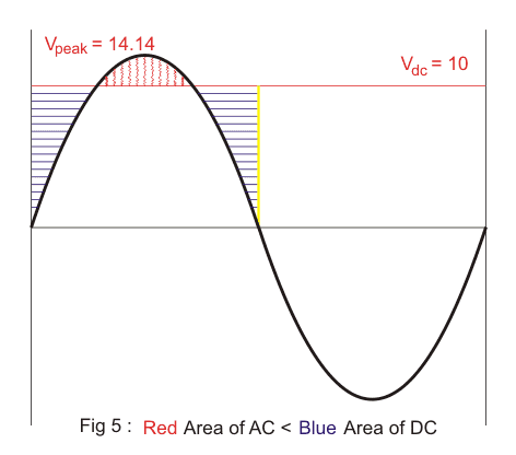 We found that by decreasing the peak voltage Vpeak up to √2 times DC voltage we get same amount of power flowing in both the circuits. When the AC voltage signal supply same amount of power as in DC then that value of DC voltage is called root mean square or rms value of AC.
We are always concerned about how much power is flowing through our circuits irrespective of how much electrons are needed to supply that power and that is the reason why we always use the rms value of AC supply instead of average value everywhere in AC system.
We found that by decreasing the peak voltage Vpeak up to √2 times DC voltage we get same amount of power flowing in both the circuits. When the AC voltage signal supply same amount of power as in DC then that value of DC voltage is called root mean square or rms value of AC.
We are always concerned about how much power is flowing through our circuits irrespective of how much electrons are needed to supply that power and that is the reason why we always use the rms value of AC supply instead of average value everywhere in AC system.
Now our AC voltage should supply the same amount of power. But when we switched-on the supply surprisingly, we found that AC voltage is supplying more power than the DC. Because an average value of AC supplies same amount of charges but not the same amount of power. So, to get same amount of power from our AC supply we must decrease our AC supply voltage.
We found that by decreasing the peak voltage Vpeak up to √2 times DC voltage we get same amount of power flowing in both the circuits. When the AC voltage signal supply same amount of power as in DC then that value of DC voltage is called root mean square or rms value of AC.
We are always concerned about how much power is flowing through our circuits irrespective of how much electrons are needed to supply that power and that is the reason why we always use the rms value of AC supply instead of average value everywhere in AC system.
Conclusion
Average value of an AC current represent the equal amount of charges in DC current.
 RMS value of an AC current represent the equal amount of power in DC current
 AC current takes less amount of charges to supply the same amount of DC power.
RMS value of an AC current represent the equal amount of power in DC current
AC current takes less amount of charges to supply the same amount of DC power.
SI System of Units
Units are defined as those tools using which we can measure any physical quantities effectively. For example, if we want to measure length then that can be measured in meters, centimeters, feet etc, again if we have to measure mass then that can be measured in kilograms, grams etc. So from the above example we can say that there are many units which can be used to measure a particular quantity.
Now if we take the other physical quantities also then there are many units available for a particular quantity. Now, this leads to the confusion in ourselves, one may ask that which one should we choose and which one we should not choose for measurement. If many units available than there may be some conversion factor to convert it into the other unit but that is very clumsy and also there is a high chance of error in doing that and if we require to measure that particular unit in the third unit that is available for the quantity, we may end up getting the erroneous result.
Now if we take the other physical quantities also then there are many units available for a particular quantity. Now, this leads to the confusion in ourselves, one may ask that which one should we choose and which one we should not choose for measurement. If many units available than there may be some conversion factor to convert it into the other unit but that is very clumsy and also there is a high chance of error in doing that and if we require to measure that particular unit in the third unit that is available for the quantity, we may end up getting the erroneous result.
So there is an absolute necessity for choosing standard quantities in measurement. In this case, what we do is we choose a single unit for a particular quantity that unit is known as standard unit. Most of the measurements are done in that unit. So the measurement becomes simple but also it gives importance in a single unit for a particular quantity.
SI System of Units
Most of us know what SI units are but we do not know what SI means. It simply means international systems of units. The units which are taken in measuring physical quantities are collectively called as SI units. It is developed and recommended by General conference on Weights and measures in 1971 for international usage in scientific, technical, industrial and commercial work. Now the problem arises is, what units should we choose? The units chosen must have the following qualities-- It must have a suitable size.
- It should be accurately defined.
- It must have an easy access.
- It must be time independent.
- It should not change with the change in physical quantities.
SI Base Units
| Quantity | Unit | Symbol |
| Length | meter | m |
| Mass | kilogram | kg |
| Time | second | s |
| Temperature | kelvin | K |
| Amount of substance | mole | mol |
| Electric current | ampere | A |
| Luminous intensity | candela | cd |
| Plane angle | radian | rad |
| Solid angle | steradian | sr |
Advantages of SI System of Units
- It is a coherent system of units.
- It is a rational system of units.
- SI is a metric system.
Conclusion of SI System of Units
Though it has great advantages and now we use SI units for most of the measurements but it is not free from disadvantages too. It has disadvantages such as it mainly focuses on only one unit so the importance of other units is diluted. Also the SI unit cannot always accurately define a quantity. For example, in case of a measurement of the area covered by a house we use square feet as the unit of area in most of the cases, so in those situations we may have to convert to the SI units which is not desirable, such a case may arise in the other situations also but the advantages of SI systems are more dominant so it is so popular and we use it quite often.Electrical International Symbol
| Name Of Symbol | Mark Symbol |
| Concealed Wiring |  |
| Conduit Wiring |  |
| Direct Concealed Wiring |  |
| Multiple Conductor Line |  |
| Tanking Wiring |  |
| Cable Termination |  |
| Branching Box |  |
| Electrical Appliance |  |
| Telecom Indication Socket Outlet |  |
| Arial Socket Outlet of TV and Radio |  |
| Florescent Lamp |  |
| Electric Bell |  |
| Electric Door Opener |  |
| Buzzer |  |
| Current Impulse Switch |  |
| Electric Line Permanent Point |  |
| One Way Single Pole Switch |  |
| One Way Two Pole Switch |  |
| Two Way Single Pole Switch |  |
| Intermediate Switch |  |
| Push Button Switch |  |
| Single Lamp |  |
| Dreamer Switch |  |
| Single Socket Outlet |  |
| Double Socket Outlet |  |
| Arial |  |
| Surface Wiring |  |
| Electric Motor |  |
| Electric Heater |  |
| Electric Water Heater |  |
| Electric Cooking Range |  |
| Refrigerator |  |
| Electrical Wiring Connection Symbol/Mark |  |
| Terminal Strip |  |
| Branching Box |  |
| Earthing |  |
| Electric Fuse |  |
| Electric Lamp |  |
| Socket Outlet |  |
| Electric Motor, Single Phase |  |
| Electric Motor, Three Phase |  |
| Electric Cell |  |
| Thermal & Electro magnetic trippers switch three Pole |  |
| Electric Measuring Instrument |  |
| Volt Meter |  |
| Electromagnetic Tripper Switch Single Pole |  |
| Magnetic Conductor with three Main Conduction |  |
| Washing Machine |  |
| Dish Washing Machine |  |
| Electric Meter |  |
| House Connection Box |  |
| Push Button Switch |  |
| Florescent Lamp’s Choke Coil |  |
| Starter of Florescent Lamp |  |
| Resistor |  |
| Inductance |  |
| Capacitor |  |
| Stair Case Time Switch |  |
| Rectifier |  |
| Transformer |  |
| Thermal Tripper Switch, Single Pole |  |
| Thermal Tripper Switch Three Pole |  |
| Main Switch |  |
| Electric Door Opener |  |
| Ear Phone |  |
| Power Pack |  |
| Circuit Breaker (MCCB) |  |
| Limit Switch |  |
| Electromagnet Conductor |  |
| Electromagnet Relay |  |
| Time Lag Relay |  |
| Generator DC |  |
| Generator AC |  |
| Motor AC & DC |  |
| Ampere Meter |  |
| Manual Multiple Switch single pole.Four way shown in single way. |  |
| Microphone |  |
| Loudspeaker |  |
| Electro Magnetic |  |
| Phase Line |  |
| Proper connection Line |  |
| Neutral Line |  |
| Earth Line |  |
| Signal Line |  |
| Distribution Box/Panel Board |  |
| Thermal Relay |  |
| Ceiling Rose |  |
| Magnetic Conductor Tripper Three Main Contact |  |
| Change Over Switch |  |
| Wire Overlay Crossing |  |
| Plug and Socket |  |
| Two-pin Plug socket(with & without switch) |  |
| Three-pin Plug socket(with & without switch) |  |
| Ceiling Lamp Outlet |  |
| Wall Lamp Outlet |  |
| Ceiling Fan |  |
| Bracket Fan |  |
| Exhaust Fan |  |
| Fan Regulator |  |
| Indicator Switch |  |
| Electromagnet Relay |  |
| Lamp (with Bracket) |  |
| AC Current |  |
| Direct and Alternating Current |  |
| Movable Iron Type Machine |  |
| Main Fuse Board (without Switch) |  |
| Main Fuse Board (with Switch) |  |
| Switchless Distribution Fuse Board |  |
| Distribution Fuse Board(with switch) |  |
| Air Circuit Breaker |  |
| Oil Circuit Breaker |  |
| Relay |  |
| Lighting Arrester |  |
| Starter (Motor) |  |
| Star Delta Starter |  |
| Emersion Heater |  |
| Hanging Lamp |  |
| Water Type Lamp |  |
| DC Current |  |
| Movable Permanent Magnetic Type Machine |  |
| Battery |  |
Cyclotron Basic Construction and Working Principle
Before understanding the basic working principle of Cyclotron it is necessary to understand force on a moving charged particle in a magnetic field and also motion of the charged particle in the magnetic field.

Force on a Moving Charged Particle in a Magnetic Field
When a current carrying conductor of length L metre with current I ampere placed perpendicularly in a magnetic field of flux density B Weber per metre square, then the force rather to say magnetic force acting on the conductor would be
Now, let us consider there are total N number of mobile free electrons in the conductor lie in length L metre causing the current I ampere.
 Where, e is the electric charge of one electron and it is 1.6 × 10⁻¹⁹ coulomb.
Now from equation (1) and (2) we get
Where, e is the electric charge of one electron and it is 1.6 × 10⁻¹⁹ coulomb.
Now from equation (1) and (2) we get
 Here, N number of electrons causing current I ampere, and consider that they travel length L metre in time t, therefore drift velocity of the electrons would be
Where, e is the electric charge of one electron and it is 1.6 × 10⁻¹⁹ coulomb.
Now from equation (1) and (2) we get
Here, N number of electrons causing current I ampere, and consider that they travel length L metre in time t, therefore drift velocity of the electrons would be
From equation (3) and (4), we get
 It is the force acting on N number of electrons in the magnetic field hence force on a single electron in that magnetic field can be

It is the force acting on N number of electrons in the magnetic field hence force on a single electron in that magnetic field can be
Motion of Charged Particle in a Magnetic Field
When a charged particle moves in a magnetic field, there would be extreme two conditions. The particle moves either along the direction of the magnetic field or it moves perpendicular to the magnetic field. When the particle moves along the axis of the direction of magnetic field, magnetic force acting on it, Hence there will be no force acting on the particle, hence no change in the velocity of particle and hence it moves in straight line with constant speed.
Now if the charged particle moves perpendicular to the magnetic field then there will be no change in the speed of the particle. This is because the force acting on the particle is perpendicular to the motion of the particle hence the force will not do any work on the particle so there will be no change in the speed of the particle.
But this force acting on the particle perpendicular to its motion and the direction of the motion of the particle will change continuously. As a result the particle will move in a in the field in a circular path of a constant radius with constant speed.
If the radius of the circular motion is R metre then
 Now,
Now,
 Hence radius of the motion depends upon the velocity of the motion.
Angular speed and time period are constant.
Hence radius of the motion depends upon the velocity of the motion.
Angular speed and time period are constant.
Now,
Hence radius of the motion depends upon the velocity of the motion.
Angular speed and time period are constant.Basics Principle of Cyclotron
This concept of motion of charged particle in a magnetic field was successfully employed in an apparatus called cyclotron. Conceptually this device is very simple but it has huge uses in the field of engineering, physics and medicine. This is a charged particle accelerating device. The motion of the charged particle under perpendicular magnetic field is solely applied in the apparatus named cyclotron.Construction of Cyclotron
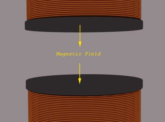
This device basically has three main constructional parts- Large sized electromagnet to create uniform magnetic field in between its two face-to-face placed magnetic opposite poles.
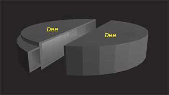
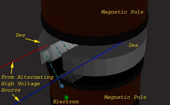
- Two low height hollow half cylinders made of high conductive metals. These components of cyclotron are called Dees.
- A high-frequency alternating high voltage source.
Constructional Details
The Dees are placed face to face in between the electromagnetic poles. The dees are so placed, that the straight edge will be face-to-face with small gap between them. Also the magnetic flux of the electromagnet cut these Dees exact perpendicularly. Now these two Dees are connected to two terminals of an alternating voltage source so that if one Dees is in the positive potential than other will be in exact opposite negative potential at same time. As the source is alternating the potential of the Dees are altered according to the frequency of the source. Now if a charged particle is thrown from a point near to the centre of one Dees with certain velocity V1. As the movement of the particle now perpendicular to the externally applied magnetic field, there will be no change of velocity but the charged particle will follow a circular path of radius Where, m gram is the mass and q coulomb is the charge of the thrown particle and B Weber/metre2 is the flux density of externally applied perpendicular magnetic field.
After travelling π radians or 180o with radius R1 the charged particle comes to the edge of the Dee. Now the time period and frequency of the applied voltage source is so adjusted with the time period of circular motion that is
Where, m gram is the mass and q coulomb is the charge of the thrown particle and B Weber/metre2 is the flux density of externally applied perpendicular magnetic field.
After travelling π radians or 180o with radius R1 the charged particle comes to the edge of the Dee. Now the time period and frequency of the applied voltage source is so adjusted with the time period of circular motion that is
 That the polarity of the other Dee becomes opposite that of the charged of the particle. Hence due to attraction of the Dee ahead the moving particle and also due to repulsion of the Dee in which the particle is now situated, the particle gets extra kinetic energy.
 Where ν1 is the velocity of the particle at previous Dee and ν2 is the velocity of the particle in next Dee. Now the particle will move with this greater velocity with radius R2 metre.
 Again due to constant perpendicular magnetic field the particle travels another half cycle with this new radius R2 metre and comes to the edge of present Dee. When it comes to this edge, the ahead Dee again becomes in opposite polarity of the behind and the particle crosses the gap between Dees with gain of kinetic energy qV and hence again there is gain of velocity and radius of the circularly travelling charged particle. In this way the charged particle follows a spiral path of motion with continually increasing velocity. Therefore the charged particle gets sufficiently high required velocity before leaving the cyclotron gun head.
The frequency of voltage source say f.
Again due to constant perpendicular magnetic field the particle travels another half cycle with this new radius R2 metre and comes to the edge of present Dee. When it comes to this edge, the ahead Dee again becomes in opposite polarity of the behind and the particle crosses the gap between Dees with gain of kinetic energy qV and hence again there is gain of velocity and radius of the circularly travelling charged particle. In this way the charged particle follows a spiral path of motion with continually increasing velocity. Therefore the charged particle gets sufficiently high required velocity before leaving the cyclotron gun head.
The frequency of voltage source say f.
 Here, 2π is constant, m, q and B are known hence T can be calculated and hence frequency of the voltage source would be

Application of Cyclotron
There are mainly two types of application of cyclotron. One is in lavatory of different physics experiments when highly accelerated photons are required. Also highly accelerated photons are used to irradiate tissues.Space Charge
Accumulation of charges in a particular region is referred to as space charge. The space in which the charges concentrate can be either free space or a dielectric. Further, this cloud of charges might be mobile or immobile in nature. Let us try to understand better with the help of examples.
Example 1: Now, consider the case where we have brought a p-type semiconductor in contact with an n-type semiconductor. As is well known, n-type semiconductor material has excess electrons while the p-type material is depleted of them. Thus, when these two kind of materials are brought in-contact, the electrons will start moving from n-type to p-type.
This causes the electrons and holes present near the junction to recombine with each other. As a result, a certain region around the junction will be depleted of mobile charge carriers. This region is nothing but the space charge region which has immobile ions (Figure 1a).

Example 2: Next, let us assume that we have an electron tube supplied with power. In such a situation, the electrons will be ejected from the cathode terminal and will start moving towards the anode.
However these electrons cannot reach their destination instantaneously i.e. they will take some amount of finite time to complete their journey. As a result, these electrons can accumulate near the cathode end of the device forming a cloud of negative charges. This leads to the formation of negative space charge region (Figure 1b) which can move under the influence of applied electric field.
Example 2 indicates that the basic reason which leads to the accumulation of charges is the fact that the rate of removal is less when compared to the rate of accumulation. That is, the cathode terminal emits more number of electrons than those which travel towards the anode. However, even trapping of charges, drift and diffusion can contribute for the occurrence of space charge region. Further if the polarity of the charges constituting the space charge is same as that of the electrode associated, then they are called homocharges. On the other hand, if their polarities differ from each other, then they are referred to as heterocharges.
Consequences of Space Charge
The space charge effect poses a challenge by affecting the conversion efficiency and the output power of thermionic converters. This is because when such an electron cloud is present around the metal surface, it poses an additional barrier for the electrons which are supposed to reach their final point. This inhibition for the movement of electrons is experienced in the form of repulsion for the emitted electrons from the electrons which are present in the cloud. The space charge effect which occurs in the dielectrics also leads to the breakdown of electrical components like capacitors. This is because, when high voltages are applied, the electric charges emitted from the electrode get trapped within the gas surrounding it. The same effect is also seen to cause the failure of power cables which carry high voltages. However, space charge effect is also seen to be advantageous in certain scenarios. For example, the presence of space charge region creates a negative EMF on certain tubes which is analogous of providing a negative bias to it. This is inturn meritorious as it helps the engineers to have a better control over the process of amplification, thus improving its efficiency. Yet another example noteworthy of being mentioned is that the space charge has a tendency to reduce the shot noise. This is because, basically the space charge affects the easy movement of charges along their path. This inturn reduces the number of charges which arrive randomly, thereby reducing their statistical variation which is nothing but the shot noise.Ionization Energy
The ability of an element to give away its outermost electrons to form positive ions is manifested in the amount of energy supplied to its atoms sufficiently enough to take away the electrons out of them. This energy is known as Ionisation Energy. Simply speaking, the Ionisation Energy is the energy supplied to an isolated atom or molecule to knockout its most loosely bound valence shell electron to form a positive ion. Its unit is electron-volt eV or kJ/mol and is measured in an electric discharge tube in which a fast-moving electron collides with a gaseous element to eject one of its electrons. The lesser Ionisation Energy (IE), the better the ability to form cations.
 This can be explained with the Bohr model of an atom, in that it considers a hydrogen-like atom in which an electron revolves around a positively charged nucleus due to the columbic force of attraction and the electron can only have fixed or quantized energy levels. The energy of a Bohr model electron is quantized and given as below :
 Where, Z is the atomic number and n is the principal quantum number where n is an integer. For a hydrogen atom, Ionisation energy is 13.6eV.
This can be explained with the Bohr model of an atom, in that it considers a hydrogen-like atom in which an electron revolves around a positively charged nucleus due to the columbic force of attraction and the electron can only have fixed or quantized energy levels. The energy of a Bohr model electron is quantized and given as below :
Where, Z is the atomic number and n is the principal quantum number where n is an integer. For a hydrogen atom, Ionisation energy is 13.6eV.
The Ionisation Energy (eV) is the energy required to take the electron from n = 1 (ground state or most stable state) to infinity. Hence taking 0 (eV) reference at infinity, the Ionisation Energy can be written as : The concept of Ionisation Energy supports the evidence of Bohr model of atom that the electron can revolve around the nucleus in a fixed or discrete energy levels or shells represented by the principal quantum number ‘n’. As the first electron goes away from the vicinity of the positive nucleus, then greater energy is required to remove the next loosely bound electron as the electrostatic force of attraction increases, i.e., the second Ionisation Energy is greater than the first one.
The concept of Ionisation Energy supports the evidence of Bohr model of atom that the electron can revolve around the nucleus in a fixed or discrete energy levels or shells represented by the principal quantum number ‘n’. As the first electron goes away from the vicinity of the positive nucleus, then greater energy is required to remove the next loosely bound electron as the electrostatic force of attraction increases, i.e., the second Ionisation Energy is greater than the first one.
For example, the first ionization energy of Sodium (Na) is given as :  And its second Ionisation Energy is
And its second Ionisation Energy is
Hence, IE2 > IE1 (eV). This is also true if there are K number of ionisations, then IE1 < IE2 < IE3……….< IEk
Metals have low Ionisation Energy. Low Ionisation Energy implies better conductivity of the element. For example, the conductivity of Silver (Ag, atomic number Z = 47) is 6.30 × 10⁷ s/m and its Ionisation Energy is 7.575 eV and for Copper (Cu, Z = 29) is 5.76 × 10⁷ s/m and its Ionisation Energy is 7.726 eV. In conductors the low Ionisation Energy causes the electrons to move throughout the positively charged lattice, forming an electron cloud.
Factors Affecting Ionisation Energy
In the periodic table, the general trend is that the Ionisation Energy increases from left to right and decreases from top to bottom. So the factors affecting ionization energy can be summarised below:
- Size of the Atom: The Ionisation Energy decreases with the size of the atom because as the atomic radius increases the columbic force of attraction between the nucleus and outermost electron decreases and vice-versa.
- Shielding Effect: The presence of inner shell electrons shield or weaken the columbic force of attraction between the nucleus and the valence shell electrons. Hence ionization energy decreases. The number of inner electrons means more shielding. However, in the case of gold, the Ionisation Energy is greater than silver even if the size of gold is more than silver. This is due to the weak shielding offered by the inner d and f orbitals in case of gold.
- Nuclear Charge: The more the nuclear charge, the more it will be difficult to ionize the atom due to more attraction force between nucleus and electrons.
- Electronic Configuration: The more stable the electronic configuration of the atom, the more difficult is to withdraw an electron hence more Ionisation Energy.

thanks for sharing a knowledge "What Is an Ammeter "
ReplyDeleteToday I’m going to share with you the List of Working Jio TV ID & Password.
ReplyDeletethanks for sharing a knowledge "building skeleton "
ReplyDeleteThanks for the article. Quite informative and subtle details. What is Compressive Strength of Plastics | The Complete Guide - PlasticRanger is a must for certain applications
ReplyDeleteThis comment has been removed by the author.
ReplyDeletejig fixtures: A dance and apparatus are work holding gadgets utilized in machining tasks as a specialist of help. They secure, backing or mount a workpiece accurately on the pieces of a CNC machine.
ReplyDelete